Equipment & Tools
V552 - 5 Axis vice
The V552 is a 5″ x 5″ self centering 5 axis vise. It was created with the goal of fitting a self centering vise on a small pallet for robotic loading cells. It has quickly become a favorite vise for shops utilizing smaller palletized systems as well as smaller rotary tables where clearance is a major concern. Its compact foot print and low profile design has made it the most popular choice for a majority of machine shops across the world. The V552 is built from heat treated 4100 series steel and is precision ground and hard milled to ensure accuracy and repeatability.
Coordinate Measure Machine
A coordinate measuring machine (CMM) is a device used in the measurement of the physical geometrical characteristics of an object. These machines can be manually controlled by an operator or they may be computer controlled. Measurements are defined by a probe attached to the third moving axis of this machine.
Design Tips & Aids
FreeCAD
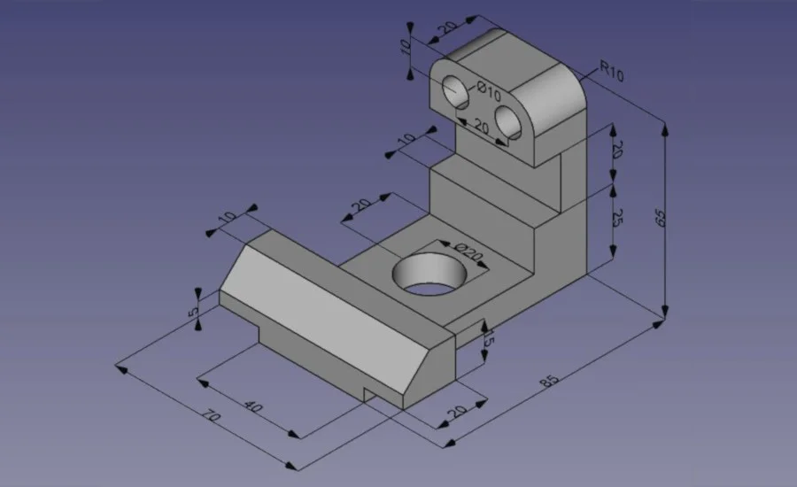
FreeCAD is a multiplatfom (Windows, Mac and Linux), highly customizable and extensible software. It reads and writes to many open file formats such as STEP, IGES, STL, SVG, DXF, OBJ, IFC, DAE and many others, making it possible to seamlessly integrate it into your workflow.
Sketchup
SketchUp debuted in August 2000 as a general-purpose 3D content creation tool and was envisioned as a software program "that would allow design professionals to draw the way they want by emulating the feel and freedom of working with pen and paper in a simple and elegant interface, that would be fun to use and easy to learn and that would be used by designers to play with their designs in a way that is not possible with traditional design software. It also has user friendly buttons to make it easier to use."
GEOMETRIC DIMENSIONING AND TOLERANCING (GD&T)
Geometric Dimensioning and Tolerancing (GD&T) is a language of symbols and standards designed and used by engineers and manufacturers to describe a product and facilitate communication between entities working together to produce something.
When you look at machined parts, they look flat and straight, but if you were to view the parts with calipers, you would find that there are imperfections all over the parts. These variations (imperfections) are allowed within the tolerance limits (constraints) placed on the parts. In order to understand geometric tolerancing, it helps to think of parts as having varying degrees of imperfection.
The engineer or designer should strive to keep tolerances as large as possible while preserving the function of the part. Small tolerances can increase cost in the manufacturing, inspection, and tooling of parts. Tight tolerances are sometimes necessary, but it’s important to keep them in perspective.


